Create a circuit
- Name your circuit
- Label all inputs and outputs
- Label all logic gates
- Label wires
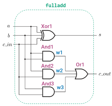
Example :
module fulladd (a, b, c_in ,s ,c_out);
	input a, b, c_in;
	output s, c_out;

	wire w1, w2, w3;

	// Note : we can ommit the gate names for a simpler looking circuit
	and And1(w1, a, b);
	and And2(w2, a, c_in);
	and And3(w3, b, c_in);

	or Or1(c_out, w1, w2, w3);
	xor Xor1(s, a, b, c_in);
endmodule
Which gives:
If we want to use this full adder, we instantiate it using
fulladd stage1 (.c_in(c_in), .a(a), .b(b), .s(s), .c_out(c_out));We have to specify the name of the instance. We reference the inputs outputs of the full adder by using .name, and put in the parantheses what it amounts to.
module adder_4_bit(Cin, A, B, S, Cout);
	input Cin;
	input [3:0] A,B; // 4-bit vector
	output [3:0] S; // 4-bit vector
	output Cout;

	wire [3;1] W; // 3 bit vector

	fulladd stage0 (.cin(Cin),  .a(A[0]), .b(B[0]), .s(S[0]), .c_out(C[1]));
	fulladd stage1 (.cin(C[1]), .a(A[1]), .b(B[1]), .s(S[1]), .c_out(C[2]));
	fulladd stage2 (.cin(C[2]), .a(A[2]), .b(B[2]), .s(S[2]), .c_out(C[3]));
	fulladd stage3 (.cin(C[3]), .a(A[3]), .b(B[3]), .s(S[3]), .c_out(Cout));
endmodule