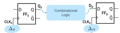
In practice, the outputs of sequential logic elements connects to the inputs of other sequential elements.
For correct operations, timing constraints must be met.
A signal on input of a DFF must be stable during (before and after) the rising edge of the clock (so that the correct data gets read)
Metastability
If a signal is not stable around the rising clock edge, then a DFF will oscillate at a value between and , before settling on a random value.
For a circuit to meet those timing constraints, then all FF outputs to FF inputs must meet timing constraints. In order to do so, we:
- Must have a stable signal for before and after the rising clock edge
A signal goes through a few steps:
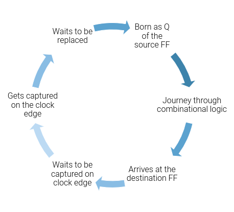
Born as of the source FF
There can be a delay between and
Updating the output takes some clock-to- delay
Journey through combinational logic
It takes time of for the signal to be processed during the combinational logic.
During this time the signal outputted can be unstable
Arrives at the Destination FF
After a total time of , the signal arrives at the destination where it will be captured
Waits to be captured
It waits — in a stable manner — at the input of the next flip flop. This wait must at least be as long as the setup time
Gets captured on the clock edge
The destination takes the value on its input, and works through memorizing it. (Which can take some time)
Waits to be replaced
The clock edge that captured is passed. The wait must be at least as long as the hold time (And it must be stable!!).
Meeting time constraints
To setup the signal, we have the following:
For and , we must have the inequality given by
The worst case time constraint can be rewritten as
We have an algorithm to find this maximum frequency
Algorithm
- Identify all -to- paths
- For every path a. Compute its longest combinational delay b. Find the shortest clock period that satisfies this path’s setup-time constraint
- Find the shortest clock period that satisfies the setup-time constraints of all those paths
- Compute
To hold the signal, we have the following:
For and , we have:
The worst-case constraint is written as
To find hold-time violations, we have
Algorithm
- Identify all -to- paths
- For every such path a. Compute its shortest combinational delay b. Verify if the hold-time constraint is satisfied
Clock Skew
In real circuits, the clock signal may not arrive at all FFs at the same time, due to the wires
We call this delay clock skew — which is given by
This should not be neglected!!
We have both a negative and a positive clock skew
- Negative:
- Positive:
With clock skew, we see life of the D signal change slightly, as we need to account for the possible delays in clocks for the hold and the setup time
The expression that must hold has the skew added in:
And we have the worst-case scenario as
And to meet hold time constraints, we have
And the worst-case scenario as
Positive time skew INCREASES max frequency